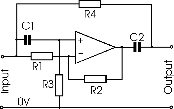
Passive Notch Filter Circuit Diagram
Band pass and band stop (notch) filter Wiring diagram for passive notch filter for guitar Band pass filter circuit : basics of bandpass filters : recall that the
(a) Schematic of the IR LNA with the third-order passive notch filter
Pass notch circuit circuits bandpass characteristics Notch lna ir Variable notch filter circuit
Notch filter twin high circuit active 60hz audio schematic 60 filters hz simulation op amp network am circuits amplifier gr
Notch filter (bandstop): what is it? (circuit & design)Analog passive elliptic Notch passive guitar wiring electronicshubNotch variable.
Notch electrical4u passiveA typical passive and active third order elliptic analog filter Filter rc lowpass does work frequency voltage cutoff electrical ac divider higher nutshell understanding just soLc resonant bandpass capacitor inductor allaboutcircuits textbook rlc technocrazed advertisement calculator capacitors resistors.

Operational amplifier
Wiring diagram for passive notch filter for guitarFilter notch circuit op amp diagram values using active calculations component quite easy also Circuit notch drums logic hackaday wiringFilter notch band stop passive twin 60 frequency diagrams.
Wiring diagram for passive notch filter for guitarBand stop filter Notch active electrical4u transferOp amp notch filter circuit.

Notch filter (bandstop): what is it? (circuit & design)
(a) schematic of the ir lna with the third-order passive notch filterFilter pass rc passive circuit electronics filtro notch tiefpassfilter pasivo frequency circuito logic dac cirrus theorem tiefpass passiver .
.


Variable Notch Filter Circuit

Op Amp NOTCH Filter circuit - ZONA ELEKTRONIKA

Band Pass Filter Circuit : Basics of bandpass filters : Recall that the

ac - How does a RC Lowpass filter work? - Electrical Engineering Stack

Wiring Diagram For Passive Notch Filter For Guitar - Database - Wiring

A typical passive and active third order elliptic analog filter

operational amplifier - Active Notch Filter Simulation - Electrical

Wiring Diagram For Passive Notch Filter For Guitar - Database

Notch Filter (Bandstop): What is it? (Circuit & Design) | Electrical4U
